 |
- Jamma
- 'Japanese Amusement Machine Manufacturers Association'
A standard pin-out for pcb's. Makes it possible to 'Plug & Play' jamma-compatible games (read pcb's) in a jamma-cabinet. The pinout for the jamma-conector looks like this:
|
Solder Side
|
Parts Side
|
|
GND
|
A
|
1
|
GND
|
|
GND
|
B
|
2
|
GND
|
|
+5
|
C
|
3
|
+5
|
|
+5
|
D
|
4
|
+5
|
|
-5
|
E
|
5
|
-5
|
|
+12
|
F
|
6
|
+12
|
|
- KEY -
|
H
|
7
|
- KEY -
|
|
Coin Counter #2
|
J
|
8
|
Coin Counter #1
|
|
Coin Lock Out #2
|
K
|
9
|
Coin Lock Out #1
|
|
Speaker (-)
|
L
|
10
|
Speaker (+)
|
| |
M
|
11
|
|
|
Video Green
|
N
|
12
|
Video Red
|
|
Video Sync
|
P
|
13
|
Video Blue
|
|
Service Switch
|
R
|
14
|
Video GND
|
|
Tilt Switch
|
S
|
15
|
Test Switch
|
|
Coin Switch # 2
|
T
|
16
|
Coin Switch # 1
|
|
2P Start
|
U
|
17
|
1P Start
|
|
2P Up
|
V
|
18
|
1P Up
|
|
2P Down
|
W
|
19
|
1P Down
|
|
2P Left
|
X
|
20
|
1P Left
|
|
2P Right
|
Y
|
21
|
1P Right
|
|
2P Button 1
|
Z
|
22
|
1P Button 1
|
|
2P Button 2
|
a
|
23
|
1P Button 2
|
|
2P Button 3
|
b
|
24
|
1P Button 3
|
| |
c
|
25
|
|
| |
d
|
26
|
|
|
GND
|
e
|
27
|
GND
|
|
GND
|
f
|
28
|
GND
|
- Jamma fingerboards
-
JAMMA fingerboards are edge connectors with the same pin layout as JAMMA arcade boards. The idea being, you take a non-JAMMA arcade board (or in our case PC or video console) and 'convert' it to JAMMA by soldering the correct input/outputs to the JAMMA fingerboard.
It should look something like this:
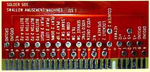
After soldering the various wires to the fingerboard, it looks like this.

|
|
|
|